Project EET-A: Engine Management Systems
Manager: Keith Glover
Investigator: Keith Glover
Research Staff: Dariusz Cieslar (PhD Student) and formerly Alex Darlington (Research Associate)
Collaborators: Nick Collings
Sponsors: Ford, Ricardo and Cambustion
Start date: 01/10/2009
Linked Projects: UT-A,
UT-C and
UT-D
Summary. This project investigates how advanced control strategies can be utilised to identify and realise engine concepts offering reduced CO2 emissions whilst satisfying customer expectations.
For many years the fuel efficiency of spark ignition engines have been significantly lower than that of compression ignition engines. Load control of spark ignition naturally aspirated engines is realised using a throttle valve. It adjusts the pressure in the intake manifold, which affects the quantity of air entering the combustion chamber during the intake phase. At part-load conditions this has a negative effect on fuel economy, as the engine has to perform work to pump the air into the combustion chamber.
Pressure charging is the concept of increasing the intake manifold pressure (MAP, boost pressure) to levels above ambient conditions, which leads to reduced pumping losses. This is the main mechanism behind higher fuel efficiencies and lower CO2 emissions of downsized engines (see Figure 1). Regarding the engine performance, it is desirable for a downsized engine to match the characteristics of a baseline unit.
The level of acceptable engine swept capacity reduction – thus reductions in CO2 emissions – depends on the capability of the pressure charging system.
| Normally Aspirated Engine |
Downsized Engine |
 |
 |
| Figure 1. Downsizing concept leads to an improved match between normal driving conditions and high efficiency range of engine operation. |
The most popular implementation of pressure charging is realised using a turbocharger. The limitations of turbo-machinery performance mean, however, that delivering satisfactory transient response at low engine speeds is challenging. This difficulty is primarily caused by the surge line of the compressor and the inertia of the entire turbocharger. In an engine equipped with a single turbocharger, the surge line of the compressor can be directly translated to the static limit of the maximum low speed steady-state torque. The second limitation is caused by the transient response of the turbocharger. This effect is called turbo-lag and is most pronounced during accelerations from low engine speeds.
Mitigating the turbo-lag effect could make even smaller engines with their potential of further reductions in CO2 emissions more acceptable for customers.
The main objectives of our research are therefore:
- To design a family of controllers for downsized/turbocharged engines, which can be easily adapted to various air-path architectures and achieve close-to-optimal transient performance in laboratory conditions
- To perform extensive testing of the transient response of a turbocharged engine with both standard and newly designed control strategies
- To investigate the fundamental limitations and trade-offs in control of the air-path of turbocharged engines, and
- To investigate the relative merits of various air-path architectures.
As a case study for using control techniques with novel air-path architectures, the use of compressed air boost assistance was selected. This can be implemented in a number of ways and both the physical arrangement and the control approach for the modified system are under investigation.
Modelling Work. Simulation using Ricardo WAVE: Ford Motor Company Ltd. has supplied a DW10C engine for our experimental work along with a high-fidelity 1-D simulation model of the same engine. The engine model is implemented in a commercial engine simulation package: Ricardo WAVE. In order to use the engine model supplied by Ford we have had to put considerable effort into expanding the range of operating conditions at which we can reliably use the model. The model was also expanded to allow investigation of our proposed compressed air assistance concepts. This expanded engine model has been integrated with Simulink to allow it to be operated in an environment that included the vehicle driveline as well as a control system.
Development of mean value model: The 1-D engine simulation works well as a virtual engine but for control purposes a simpler 0-D mean-value engine model was created. The aim for this activity was to create a model that demonstrated the same transient characteristics as the 1-D model but with significantly lower computational requirements. The simpler implementation of a mean-value engine model means that it is suitable for direct linearization to a low order model at any particular operating point, and is thus better suited to integration with control design techniques. Results comparing the performance of our mean-value model with the high-fidelity 1-D engine model show good agreement as can be seen in Figure 2 showing the engine speed and engine torque during acceleration in 3rd gear.
 |
| Figure 2. Mean-Value Model simulation results agree with 1-D WAVE model. |
Control. In many transient manoeuvres the engine performance is a function of both the air-path design and the control system. For example, during a full-load tip-in, all actuators are likely to be saturated during the initial part of the manoeuvre. The transient performance is limited by the physical characteristics of the engine and turbocharger. Therefore, the control system will be required to ensure the operation of the engine within a number of constraints (such as maximum intake manifold pressure, turbocharger speed or post-compressor temperature) and the system performance will now be limited by the ability of the control system to stay as close as possible to these limits. The tip-in manoeuvre is a test which exercises the engine over a set of rapidly changing operating points, which are usually far from steady-state equilibria. As a consequence state derivative offsets play an important role in approximating the engine behaviour with linear models. When turbocharger assistance systems are considered, the control system needs to determine the most efficient use of resources.
Model Predictive Control (MPC) is an optimisation based control framework that explicitly includes input/output constraints and therefore appears to be a good fit to the boost-assistance control problem. The approach taken in our initial work has been to develop a mean-value engine model (based on a full 1-D simulation model) and at each controller time-step to linearise this simplified model at the current engine operating point. This linear system is then used to compute the optimal inputs at that time-step. The performance of the MPC controller in transient manoeuvres has been compared with the solution to a related optimal control problem (see Figure 3) and simulations have shown it to give close to optimal performance in the manoeuvres under consideration.
 |
| Figure 3. The MPC solution for standard engine configuration results in the closed-loop performance close to the solution of optimal control problem. |
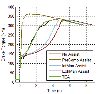
Assessment of Boost Assistance Options: Our simulation work has considered two possible types of boost assistance: electrical torque assistance directly to the turbocharger shaft and compressed air assistance. The aim of this work has been to rapidly assess the relative performance of a number of boost assistance schemes via 1-D engine simulation coupled with an MPC control approach. The effect of electric assistance (TEA) was incorporated in simulations by assuming some additional maximum torque is available at the turbocharger shaft up to a given maximum power, while compressed air assistance is simply the addition of air at some point in the engine's air-path. We have considered air-assistance in three locations: before the compressor, directly into the intake manifold (after the compressor) and into the exhaust manifold. The results of our simulation work have suggested that using compressed air directed into the exhaust manifold of the engine has some interesting possibilities and is the most promising of the boost-assistance options (see Figure 4).
 |
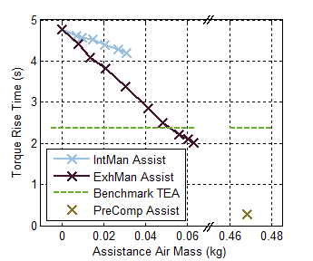 |
| Figure 4. Simulation results indicate that compressed air injection into the exhaust manifold is able to deliver transient performance similar to TEA. The compressed air in this configuration is utilised more effectively than injecting it into the intake manifold. |
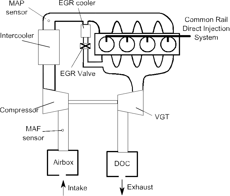
Experimental Results. A dedicated engine test rig was developed for our investigation. A production light-duty Diesel engine was supplied by Ford. We instrumented the engine and developed a testing environment for the experimental verification of simulation findings.
 |
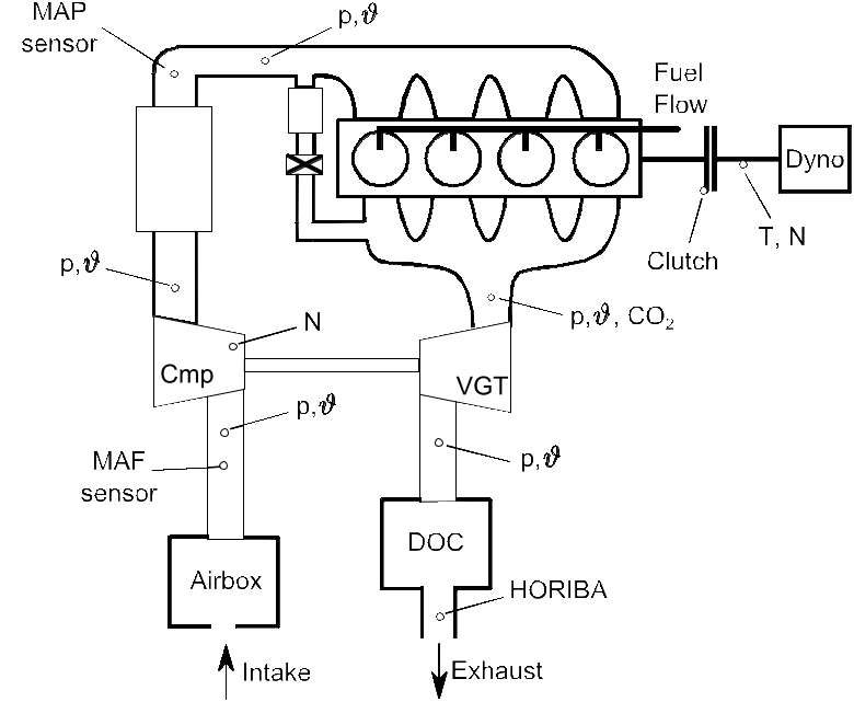 |
| Figure 5. Engine layout as supplied by Ford (left) and additional instrumentation (right). |
One concern with MPC as a control approach is the computational complexity of the algorithms, which can prevent real-time implementation. Fortunately other researchers within the Cambridge University Control Group have extensive experience in this area. With their assistance we have been able to implement our control approach on the real-time hardware used to control the engine.
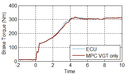
Initial tests were based on the standard engine configuration. The investigated approach resulted in the engine performance comparable to the one under original ECU control strategy, but only a modest calibration effort was required (see Figure 6).
 |
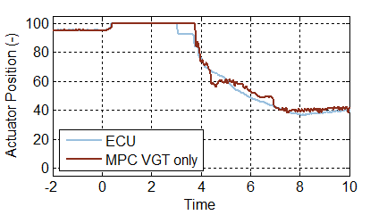 |
| Figure 6. The performance (left) and actuator position (right) of the standard engine configuration under MPC control is comparable to the operation with standard ECU strategy. |
After the inclusion of the identified actuator dynamics in the prediction model, the controller was able to ensure the operation of the engine within the prescribed limits (see Figure 7).
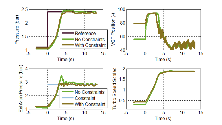 |
| Figure 7. MPC demonstrated to be able to ensure operating within physical constraints during a tip-in manoeuvre. |
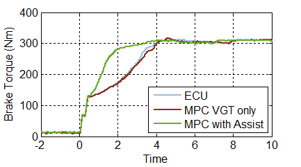
To verify the effectiveness of the compressed air assistance, the laboratory compressed air supply has been connected to the exhaust manifold via a controllable valve. The control system was realised allowing the MPC to determine the set-points for both the VGT and the assistance valve. It was observed that this system delivered a significant improvement in the transient response. The compressed air was injected only during the first two seconds of the manoeuvre. Afterwards the assistance was disabled to avoid wasting the resources (see Figure 8).
 |
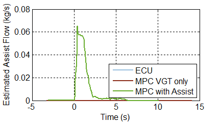 |
| Figure 8. Compressed air assistance was experimentally verified to deliver significant improvement in the transient performance (left). The compressed air injection was used only immediately after the increased torque request (right). |
With the developed experimental setup it is also possible to perform parametric studies. The effect of the pressure in the compressed air supply on engine performance was assessed. This allowed us to formulate recommendations for a possible practical implementation of the compressed air assistance system.
Further Work. The main set of objectives of the project has been achieved. Current work is focused on investigating best methods for practical implementations of the compressed air assistance. We are also focusing on disseminating the results of the project to our collaborators and wider public.
Collaboration. The project continues to benefit from regular progress meetings with Ford and Ricardo every two weeks. We have also benefitted from access to other members of the Control Group in Cambridge who have expertise in real-time implementation of MPC. This has enabled a very rapid transfer of algorithms from desktop simulations to real-time control hardware.
Publications
[DGC11a]
A. Darlington, K. Glover and N. Collings,
Diesel Cylinder Charge Properties: Feed-Forward Control and Cycle-by-Cycle Analysis Using an In-Cylinder Gas Sampling System,
SAE Technical Paper, 2011-01-0709,
2011
[CDGC12]
D. Cieslar, A Darlington, K. Glover and N. Collings,
Model Based Control for Closed Loop Testing of 1-D Engine Simulation Models,
IFAC ECOSMí12, Paris,
Oct. 2012
[DCGC12]
A. Darlington, D. Cieslar, K. Glover and N. Collings,
Assessing boost-assist options for turbocharged engines using 1-D engine simulation and Model Predictive Control,
SAE 2012 Powertrains, Fuels and Lubricants Meeting, Malmo,
Sep. 2012
[CDDHCG12]
D. Cieslar, P. Dickinson, A. Darlington, K. Hegarty, N. Collings and K. Glover,
Mean-Value Oxygen Concentration Modelling and Experimental Validation Using Fast UEGO Sensors,
Powertrain Modelling and Control, Bradford,
Sep. 2012
[CDDCG13]
D. Cieslar, P. Dickinson, A. Darlington, N. Collings and K. Glover,
A novel system for reducing turbo-lag by injection of compressed gas into the exhaust manifold,
2013 SAE World Congress,
Apr. 2013
[CDDGC14]
D. Cieslar, P. Dickinson, A. Darlington, K. Glover and N. Collings,
Model Based Approach to Closed Loop Control of 1-D; Engine Simulation Models,
Control Engineering Practise,
2014


